The ESP32 is a tiny, powerful, and inexpensive micro controller from Espressif. It has Wi-Fi and Bluetooth built in which makes it great for IoT projects. In this post I will talk about running an ESP32 on solar power. This post is not specific per-se to ESP32s and could be applied to any small 3v device.
Motivation
My family has several ponds on our property that require periodic spillway cleaning. One way to determine when it is time to clean the spillway is by looking at the water level in the pond. I wanted to create device that could periodically report the water level to the cloud so that I could monitor it remotely. I will talk through this build in later post, but here I will just talk through the power circuitry.
Approach
I needed my device to turn on for a few minutes at a time, a few times a day to collect data samples and then report them to the cloud.
Requirements
- Survive year-round outdoor weather conditions (-10°C to 40°C ambient).
- Supply well regulated 3.0v @ 100ma average, 500ma max for 3 minutes.
- Design life of 10+ years.
- Predominantly through hole components.
I broke down the problem into 3 parts: energy storage, solar panel selection, and voltage regulation.
Energy storage
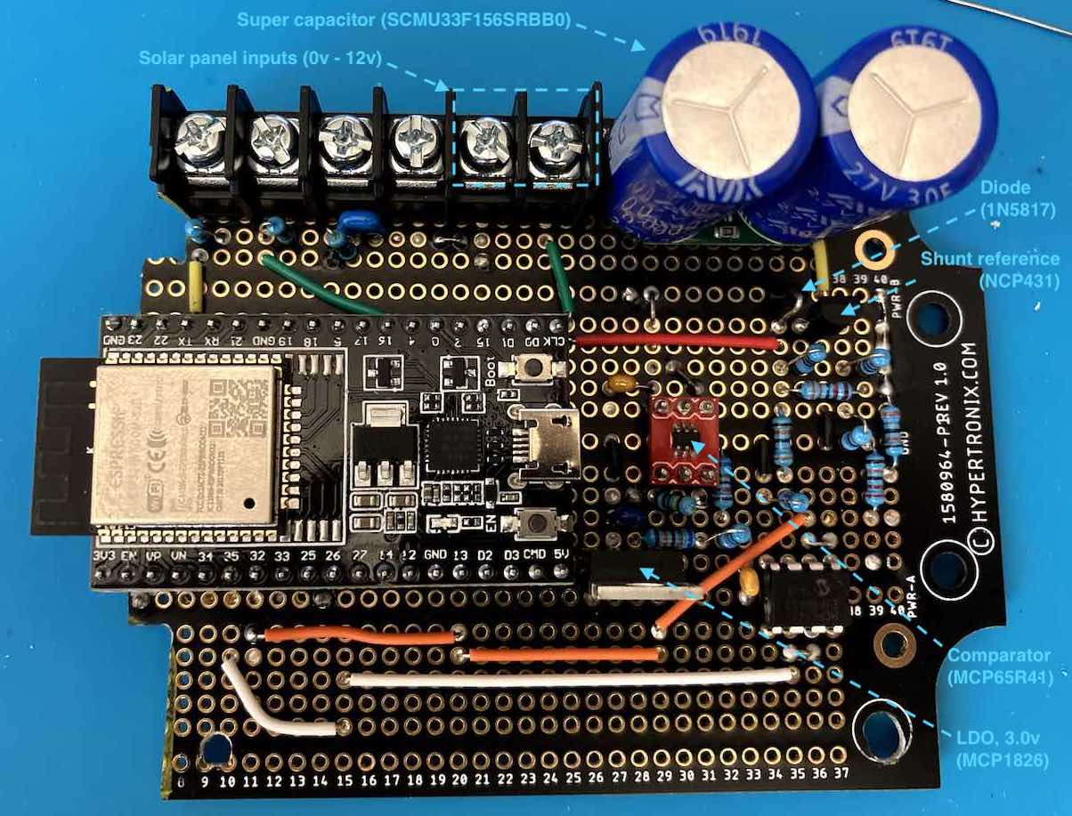
Lithium polymer batteries are a mainstay for IoT applications however due to freezing temperatures and the high cycle count, I chose to use a super-capacitor instead. Super capacitors usually are manufactured as 2.7v cells. Stacking 2 in series would provide sufficient voltage to feed a linear regulator to power the ESP32. Using this site I calculated that a 15F capacitor (with 100mΩ ESR) could supply 140ma when discharging from 5v to 3v for 3.5 minutes. I found a suitable dual capacitor module from AVX, specifically the SCMU33F156SRBB0. It is rated to 5.5v max. One thing to consider with super capacitors is they get very angry (and smokey) if you over voltage them. It seems to be a common approach to use a Zener diode across the capacitor to serve as a protection circuit for applications like this. An even better approach is to use a device like a TL431 which is an adjustable shunt-type voltage regulator. Basically the TL431 begins to conduct at a specified voltage acting as an ideal Zener diode with an adjustable Zener voltage. It can sink up to 100ma. I chose a NCP431 as it requires less power than the TI part. I setup the voltage adjust to limit the capacitor voltage to 5.2v.
I did consider some ready-made solar charge controller chips such as the SPV1040 from ST, but I felt that they were a bit expensive and would require more external passive components. I also felt that there was little to be gained in implementing MPPT as efficiency was not a driver for this project.
Solar panel and charging circuit selection
I bought a 10 pack of 5v/30ma solar panels from Amazon. In my testing under full sun they seemed to be closer to 6v/25ma. I initially wired 2 together in parallel but later went to a 2x2 configuration to allow charging at lower sun intensities. Because my charging circuit was super simple (no boost converter) the capacitor only charges if the panel voltage is greater than the capacitor voltage. I added panel discharge protection via Shottkey diode (1N5817). Again, this is not the best choice for efficiency, but they’re super simple.
Here is the charging circuit I ended up with:

Voltage regulation
Normally ESP32 modules are powered off of 5v USB and the core itself is powered via a 3.3v regulator. However, the core can run as low as 2.7v per the data sheet. I chose to use a 3.0v low-dropout linear regulator as a compromise and provide some headroom over the core’s minimum voltage. To enable and disable the voltage regulator I selected a MCP65R41 comparator. This comparator has a built in voltage reference, reducing the component count.
I initially was going to have the ESP32 boot up when the capacitor reached around 3.6v (before the capacitor was completely charged) and wait in deep sleep until the capacitor was charged, but I wasn’t able to get the ESP32 modules I had on hand to get below 9ma in deep sleep. I believe this is because the USB to serial bridge chips on these modules are powered by the 3.3v bus rather than the USB bus. This is a shortcoming of the hardware design as the CP2102 USB to serial chips can be wired to run off of USB bus power. It seems that this poor design decision comes from the reference design from Espressif itself. To work around this I adjusted the comparator to turn on only once the capacitor was nearly full. While this doesn’t remove the power drain from the CP2102 chip while the regulator is enabled, it allows the capacitor to fully charge before enabling any load.
Here is the circuit for the comparator and low-dropout regulator:

Summary
I built the circuit and it works great! I’ve had it deployed for a few months now and in daylight it turns on once an hour or so for ~4.5 minutes at a time. This runtime is achieved without using any of the low power modes of the ESP32, which could further boost the sampling time.
Stay tuned for a deeper dive on how I put this circuit to work in the board above.